Sparkwing Satellite Solar Panels
On this page we’ll explain the basics of satellite solar panels, how to find the perfect power match for your satellite, which questions to address when dimensioning your satellite solar panels and the Sparkwing off-the-shelf solar panel approach!
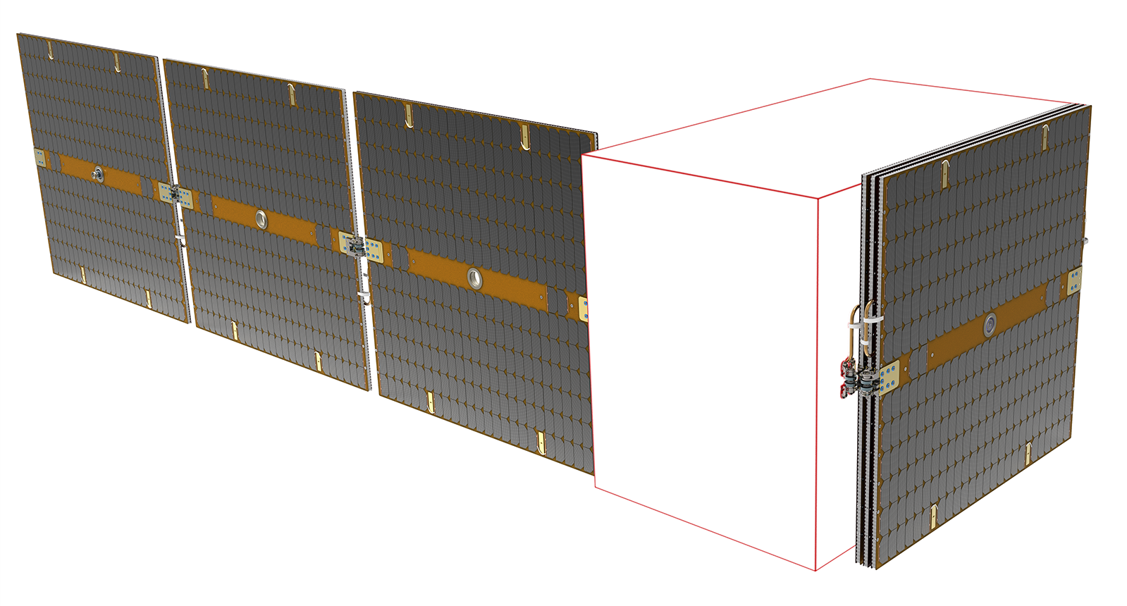
Sparkwing is the world’s first commercially available off-the-shelf solar array for small satellites. It is optimized for LEO missions requiring power levels between 100W and 2000W, and bus voltages of 36V or 50V. We offer more than twenty different panel dimensions, which can be configured into deployable wings with one, two or three panels per wing.
Let’s start with the basics (not for you pro’s)
There are no power sockets in space (yet). Satellites need power to operate once they are launched. Just like with your mobile phone, no power means no activity.
Solar panels help transform sunlight into electrical power for the operation of a satellite, making them a main source of power and thereby one of the most essential parts of a spacecraft. In the presence of sunlight, the electric power generated by solar panels charge the batteries onboard a satellite. When the satellite is away from sunlight, for example in eclipse i.e. in the Earth’s shadow, these onboard batteries ensure continuous power to the spacecraft.
The more surface a satellite solar panel has, the more sunlight it catches and thus the more electrical power it generates. In order to fit a satellite in a launcher, solar panels are folded together (‘stowed’) to the side of that satellite. Once the launcher has reached the desired orbit, the satellite is released and the solar panels are opened (‘deployed’). Once the solar panels are deployed, the satellite has wings!
A satellite can either have one single solar panel or multiple panels, depending on the power need and satellite dimensions. All solar panels combined, including the deployment mechanisms to open them in orbit, are often referred to as the ‘solar array’ subsystem.
Three things to help you find that perfect power match for your satellite (time for some big space words)
To get the right solar panels for your satellite, you need to consider the following:
1. Volume and interfaces:
- The shape of the spacecraft and rideshare or launcher volume determine the envelope you are allowed. The dimensions of your solar panels must fit this envelope. Although, local protrusions are generally allowed, you have to check on a case by case basis.
- In case of a stowed configuration, the stack height (total height of solar panels and mechanisms together) is an important parameter to consider. Due to the fixed volumes of rideshares, the stack height has impact on the available volume for the satellite itself.
- The number of sidewall interfaces determine how many stiff and load carrying points you have to foresee on the spacecraft sidewall. If interfaces have bolted connections then the interfaces need close tolerance as not to introduce any unwanted loading into the solar array.
2. Dynamic behavior – i.e. what happens to solar panels during launch and while in space:
- Stowed dynamic behavior of the solar array will have an effect on the behavior of the satellite during launch as the solar array can generally not be considered as a simple mass/spring system and has commonly lower first Eigen frequencies than electronics boxes and other equipment. Next to that, acoustic and random loads have a greater effect on the behavior of the solar array (and its transmission to the spacecraft) due to it being positioned on the outside wall of the satellite. A “coupled load analysis” (CLA) at an early stage can highlight potential coupling early on in the design. Consequently, design measures can be taken to reduce the effects.
- For most missions stability during and after maneuvers is an important consideration. E.g. to obtain focused images out of optical hardware (and many other applications requiring stability of the spacecraft), it is important that the solar array is stable relatively quickly after a maneuver to limit the settling time (which is essentially lost time). The moment of inertia and deployed behavior (Eigen frequency) of the extended solar array are therefore important aspects to consider here.
- Most RCS trusters work by releasing pulses of gas. These pulses are released at a certain frequency which should be different than the main Eigen frequencies of the solar array. This can be achieved by ensuring that the solar array deployed Eigen frequency is high or by knowing the solar array main frequencies early in the program to ensure there is no critical coupling (allowing for a less stiff Solar Array Assembly).
3. Electrical:
- Power generation varies with orbit, attitude and over the lifetime. The ‘required power’ should be your first consideration. When considering which solar array to pick, it is good to know what is included in presented power values. This includes knowing: the knock-down factors that are included, if the power is described at the solar array to spacecraft interface or somewhere else, what the orientation of the solar array is for the power listed, if the power is listed at a certain bus voltage or at the max power point voltage and which (operational) temperature is considered.
- Similarly, the minimum required voltage a solar array can provide varies over orbit and lifetime. Use the bus voltage a satellite operates on to determine the minimum required voltage and ensure that for your mission the minimum voltage guaranteed at all conditions is above the minimum voltage required.
- For smaller platforms, to reach required power values over different attitudes and to incorporate seasonal effects, you may need a root hinge opening angle that is smaller or larger than 90 degrees.
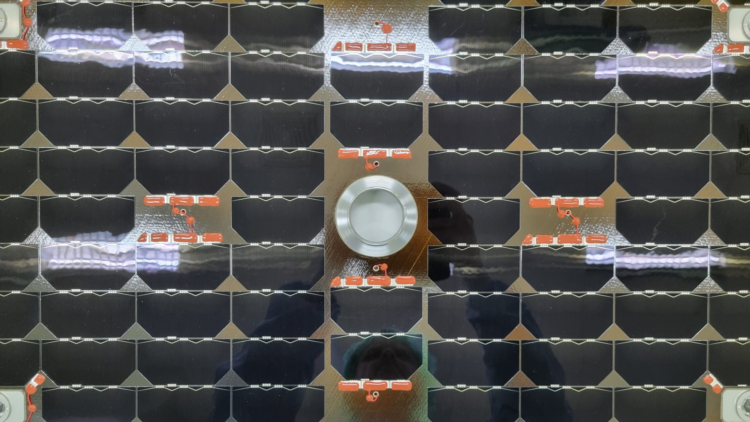
- Photo-Voltaic Assembly (PVA) lay-out can differ greatly and the stringing (cells / string), sectioning (strings per section) do determine the PCDU unit of the spacecraft (or the other way around). Stringing defines the bus voltage and sectioning will determine the maximum current. Other aspects related to the PVA lay-out are ESD and magnetic considerations.
- Atomic Oxygen (ATOX) degradation for orbits lower than 600km is something to consider as most solar arrays will have a layer in between the cells and the panels to avoid shorts between the cells and the conductive CFRP panels. This layer is most of the time not resistant against ATOX influences and therefore will need a protective layer to survive the complete lifetime without shorts.
- Telemetry might be needed for proper operations, most common is a thermistor to monitor the operational temperatures.
Dimensioning your satellite solar panels: two questions to address!
So how do you dimension your satellite solar panel? There are two main questions:
1. What is the power (Wattage) required from the solar panels?
The required power level is commonly achieved by characterizing a spacecraft’s power profile (i.e. the required level of power throughout the orbit), which depends mainly on:
- The mission type: the choice of payload / onboard instruments (e.g. for remote sensing, telecommunications, scientific, exploration) will lead to specific power requirements.
- The selected orbit (LEO, MEO, GEO, Moon, Mars, etc): determines the amount of sunlight and eclipses (thus determining battery size and charging rates), and the radiation environment (the solar panels may need ATOX protection to prevent degradation).
- Will a Solar Array Drive Mechanism (SADM) or Solar Array Drive Assembly (SADA) be used, to keep the solar panels in an optimal orientation towards to the sunlight?
2. What is the available volume (width x length x height) for the satellite solar panels?
The available space is usually determined by the size and configuration of the launcher and satellite. Also please check which sidewalls of the satellite are available for the stowed solar panel(s) and whether there are stay-out zones to be taken into account.
The Sparkwing Revolution: standardization of satellite solar panels
In the past, for every single satellite, solar arrays were designed and built to custom. With many new commercial actors in space launching large and small satellites, there is a paradigm shift in how we build solar arrays. In a growing and competitive market, customers demand reliable and affordable space products; this, in combination with technical advances (i.e. consumer electronics and other systems being adapted for space use) creates a demand for “Commercial Off-The-Shelf” (COTS) space products.
In 2018, the Sparkwing team decided to take on the challenge to create an off-the-shelf solar array for smallsats. By looking at common smallsat platforms and launchers (e.g. ESPA class and PSLV/Vega rideshare) and derived common satellite volumes therefrom. We were able to deduce standardized dimensions for solar arrays, determined common bus voltages and the optimal PVA lay-out for the standardized solar panel dimensions. As a result, we have made it happen… COTS solar arrays for satellites!

Apart from the value of getting a ready-to-launch product for an affordable price, Sparkwing comes with the following additional benefits:
- Short lead time:
The Sparkwing solar array range consist of standardized building blocks. This allows production of your panels in short time frames, i.e. 6-9 months, to achieve your program’s milestones. - High reliability:
The materials and designs of our solar panels are based on the same components that Airbus Netherlands uses for grand space missions like Rosetta, Bepi-Colombo, ExoMars, MPCV-ESM, etc, giving you high reliability, guaranteeing power throughout your mission. - Upfront clarity:
Since we have extensively characterised the Sparkwing units and models you will receive accurate data upfront, ensuring clarity and stability early in your program. - Easy integration:
Integrating our solar panels on your spacecraft is easy (6 steps) and simplified enough that it can be done by yourself, giving you maximum planning flexibility while reducing costs at the same time.